
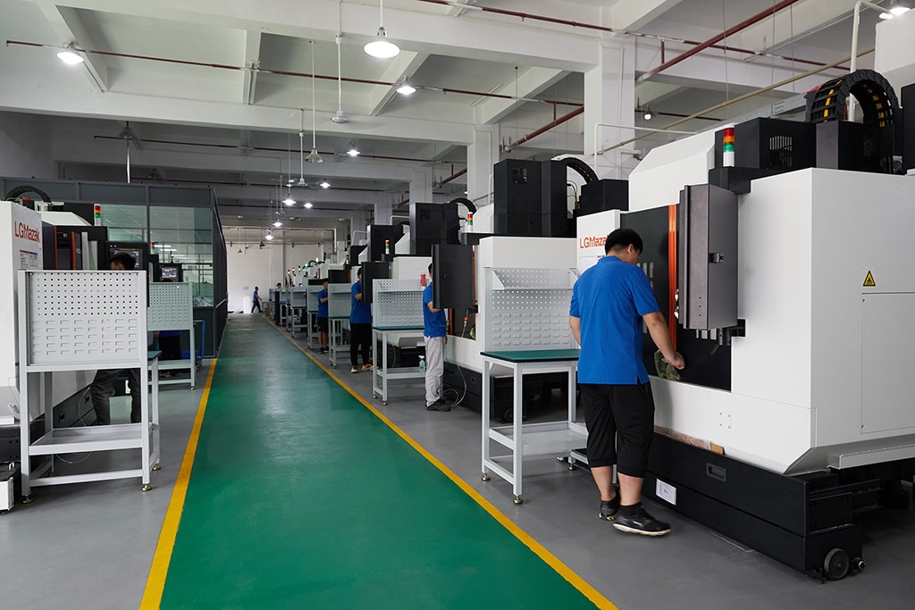
A milled part is not one surface with one tolerance; it is a collection of feature types, and each type carries its own natural limits. A pocket is limited by the reach and deflection of the tool that clears it, a slot by the ratio of its length to its width, a wall by how thin it is relative to its height, a contour by the stepover that shaped it. The drawing that treats every feature as "mill to ±0.005 and Ra 1.6" is a drawing that has outsourced the real decisions to the programmer. This guide walks the common feature types in turn and states what each can honestly hold, so the callouts on your drawing and the process on the floor finally agree.
Why is tolerance on a milled part a feature-by-feature question?
The feature is what the tool must reach and hold, and the tool's geometry and rigidity define the envelope of what is possible. A shallow open pocket is cut by a short, stiff tool that holds position easily; a deep narrow slot needs a long tool whose deflection grows with its overhang; a thin wall flexes under the cutting force and cannot be held to the tolerance a solid section would carry. Because the constraint lives in the tool and the workholding, not in the machine's nameplate, the same machine can hold ±0.003 mm on one feature of your part and struggle on another. The useful question is never "what can CNC milling hold" but "what can the tool that reaches this feature hold."
That framing also explains why two suppliers quote differently on the same drawing. One shop owns a range of small rigid tools and cuts your tight pocket feature with the right tool at the right speed; another has a standard tooling set and will reach for a longer, thinner tool that deflects. The difference is not honesty; it is tooling depth. A buyer who discusses the drawing in feature terms — "how will you reach this pocket, this slot, this wall" — is comparing the actual process rather than the average price, which is the only comparison that predicts whether the parts will measure what the drawing promises.
What can a pocket realistically hold?
A pocket is bounded by a floor and walls, and the limits are different on each. The floor is cut by the tool's flat bottom or by a facing strategy and holds position and finish well; the walls carry the tolerance on the pocket width and length, which is set by the tool diameter plus the finish pass. The depth is the villain: beyond roughly three to four times the tool diameter, a standard end mill starts to deflect and chatter in a deep narrow pocket, and the practical answer is either a longer tool with lighter cuts, a stepped roughing strategy, or a smaller pocket geometry. Ask how the deepest pocket on your drawing will be cleared, and you will hear whether the shop has sized the process to the depth or is hoping the tool behaves.
The internal corners of a pocket set another hard limit: they are machined to the radius of the cutter that reaches them, so a sharp internal corner on a deep pocket demands a small tool reaching a long way — the worst combination of fragility and reach. A buyer who can open those corner radii, or allow a larger tool to cut most of the pocket with a small tool only for the corner, gives the process room to hold the width tolerance that actually matters. The walls and the corners of a pocket are where milling quotes either plan the tooling or discover it, and the discovery is cheaper on paper than on the machine.
What limits apply to slots and thin walls?
A slot is essentially a narrow pocket, and its tolerance story is the ratio of its length and depth to its width. A slot cut by an end mill the width of the slot carries the tool's deflection along its whole length, so a long, deep, narrow slot is the feature most likely to come out tapered or wavy. The shop's answers are a shorter tool with a different strategy, a slot cut in two passes, or a ream-like finishing pass; the buyer's question is which one the quote prices. A slot width callout tighter than what the finishing tool can hold while reaching the full depth is a callout that will fight the process to the end.
Thin walls carry the opposite constraint: the part is rigid and the wall is not. A wall that is thin relative to its height deflects under the cutting pressure of every pass, so the tolerance on its thickness and the finish on its face depend on how gently it is cut — light passes, alternating sides to balance the pressure, and a finish pass with a small radial engagement. The practical rule of thumb is that the thinner and taller the wall, the wider the honest tolerance and the slower the process. A supplier that names the wall strategy for your thin features is pricing the part as it flexes; one that quotes the nominal thickness without a word is pricing a wall that will not be there.
How do the standard milling feature types perform on finish?
Finish on a milled part is set by the last pass on each surface, and the feature type decides what that pass can deliver. A flat face produced by a facing pass carries the finish of the insert nose and the feed; a side wall carries the finish of the end mill's flute and its deflection; a pocket floor finished with a small stepover shows the scallops of that stepover; a contour cut in many small steps shows the cusp height between passes. As a working map for callouts, standard milling finishes land around Ra 1.6–3.2 µm, a deliberate finish pass reaches Ra 0.8 µm, and Ra 0.4 µm and finer belongs to grinding or polishing, not to a milling cutter.
The feature that breaks the map is the sculpted or 3D contour, where the finish is written by the stepover between passes — tighten the stepover and the surface smooths while the machine time climbs steeply. On a contoured face the buyer should name the Ra and let the supplier trade stepover against time to meet it, because "smooth curve" without a number invites the cheapest stepover and the roughest acceptable result. On the flat and wall features, name the finish only where it functions, and let the natural milling finish cover the rest, because every surface pulled down a step on the Ra scale costs a pass and a price.
What tolerance should the drawing expect from milling in general?
Across the feature types, the band a serious milling service holds is ±0.003 mm on milled features in good reach and rigidity, with ±0.002 mm reserved for precision ground surfaces, and process capability of Ppk ≥ 1.67 at the initial study on key characteristics at production volume. Within that band, the honest allocation puts the tight callouts on the features the process can control — pockets and faces cut by short rigid tools in one setup — and the relaxed callouts on the features the process must nurse — deep narrow slots, tall thin walls, long reaches. A quote that claims the tight band on the impossible features is a quote that has not priced the process; one that says which features earn the band has priced the process correctly.
The buyer's mirror question is whether the drawing's tight callouts sit on features that justify them. If the assembly truly needs a deep slot held to a few microns and a tall wall kept perfectly straight, the design is asking for process heroics that belong in the quote and the lead time. If those callouts are habit rather than function — tightened because the last part had a problem somewhere else — then relaxing them is the cheapest tolerance decision on the drawing. The mature conversation is not "can you hold it" but "which of these tight callouts does the function need, and which are costing me the features that do?"
How does tool geometry set the finish and tolerance limits?
Everything above traces back to the cutter. The tool diameter sets the minimum internal corner radius and the slot width; the tool length sets the reach and the deflection; the number of flutes and the corner geometry set the finish it can leave; and the tool's sharpness decides whether it cuts or smears at the end of its life. A shop with a deep tooling library and a habit of matching the tool to the feature holds tighter numbers than an otherwise identical shop working from a thin standard set. Ask which tool cuts the features that matter on your part, and whether that tool is off the shelf or made to order — the second is where lead time and cost quietly grow.
Tool wear is the silent partner in every tolerance discussion. A new end mill cuts a slot to width; the same tool a hundred parts later has worn on its flanks and the slot closes up, or the corner radius has grown and the internal corners drift. On production runs the shop holds feature tolerance by monitoring tool life and changing cutters on schedule, and it should say so in the process plan. A supplier that treats tool wear as a consumable reality, measured and scheduled, is a supplier whose feature tolerance survives the run; one that hopes the tool lasts is pricing the first hundred parts as if they were the first ten.
How are feature tolerances and finishes measured after milling?
The instruments follow the feature. Pocket and slot widths are measured with calibrated gauges or on a CMM against the model; position and profile callouts are verified on a CMM against your datum structure; thin-wall thickness is measured where the wall is thin, not where it is supported; and finish is read with a profilometer tracing in the direction the surface was cut. The inspection report should list each feature with its instrument and its measured value, because a pocket width verified by eye is not verification. Ask which features the shop will measure on the CMM and which by gauge, and whether the CMM program uses your datum structure or the shop's convenience datum.
Agree the sampling and reporting plan when the order is placed. For a prototype, the report should carry actual values on every feature you called out; for production, it should carry the sampling plan and, on key characteristics, the SPC data reported against the Ppk ≥ 1.67 initial-study target. The report is the contract's evidence trail, and a shop that cannot state what its report will contain before the order cannot be expected to produce it after. Tie the acceptance of the order to that report, and the feature-by-feature discipline of the drawing finally meets a feature-by-feature verification.
How do you write a milled drawing that the floor can actually hit?
Write the drawing so each feature's limits are legible. Open the internal corner radii where the function allows, so the tool that clears the pocket is not fighting a corner it cannot reach. Keep the slot and wall ratios inside the ranges the process handles comfortably, or say which features are knowingly difficult and need the slow process. Put the tight callouts on the features that function and the general tolerances on the rest, and name the finish with the surface it applies to — a drawing that reads this way is a drawing a programmer can execute without guesswork and a machinist can hold without miracles.
Then confirm the plan with the numbers, feature by feature. Ask the supplier to state which tool cuts each critical feature, how the deepest pocket and the thinnest wall are handled, what tolerance each earns with its instrument, and what finish each surface will carry with its method. If the pilot part then arrives measuring what the plan promised — the pocket width inside the band, the wall straight, the contour at the Ra you named — the drawing and the process have agreed on reality. That is the only finish and tolerance story worth paying for.
Frequently Asked Questions
Why is milling tolerance a feature-by-feature question?
Because the constraint lives in the tool that reaches each feature: a shallow pocket cut by a short stiff tool holds far tighter numbers than a deep narrow slot cut by a long deflecting one. The feature, not the machine, sets the limit.
What tolerance can a milling service hold overall?
±0.003 mm on milled features in good reach and rigidity, ±0.002 mm on precision ground surfaces, with Ppk ≥ 1.67 at the initial study on key characteristics and Cpk ≥ 1.33 on general characteristics. Capability is reported per characteristic: every report names the feature, its tolerance band, the sample size, the sigma method, and the study window at volume. The band is allocated by feature, not applied blanket.
What Ra should standard milling produce?
Around Ra 1.6–3.2 µm from normal milling, Ra 0.8 µm from a deliberate finish pass, and Ra 0.4 µm and finer from grinding or polishing. On sculpted surfaces the finish is set by the stepover between passes.
How deep a pocket can be milled accurately?
Roughly three to four times the tool diameter before deflection and chatter take over. Beyond that the shop needs longer tools, stepped roughing or lighter cuts — ask how your deepest pocket will be cleared.
Why do internal corner radii matter to tolerance?
The corner is cut to the radius of the tool that reaches it. Sharp corners on deep pockets force small fragile tools to reach long distances, which is the worst case for deflection. Open the radii where the function allows.
How are thin walls best controlled?
By cutting them lightly with alternating passes to balance the cutting pressure, then a finish pass with small radial engagement. The thinner and taller the wall, the wider the honest tolerance and the slower the process.
What should the inspection report carry on a milled part?
Each feature with its instrument and measured value — pockets and slots by gauge or CMM, position against the datum structure, finish by profilometer — plus SPC on key characteristics where the contract demands capability evidence.
Feature-heavy drawing and want the tooling and tolerance plan confirmed?
Email the STEP model and toleranced drawing to [email protected] or call +86 13126536955. You get a feature-by-feature plan — the tool for each critical feature, the tolerance it earns with its instrument, and the finish method for each functional surface. See the quality page for the inspection framework and the services overview for the process scope.